本帖最后由 机器谱 于 2023-4-18 09:30 编辑
1. 功能说明
本文示例将实现R312三轴XYZ平台绘制“机器时代”空心字的功能。
2. 电子硬件
在这个示例中,采用了以下硬件,请大家参考:
主控板 | Basra主控板(兼容Arduino Uno)
| 扩展板 | Bigfish2.1扩展板
| SH-ST步进电机扩展板 | 电池 | 11.1V动力电池 | 传感器 | 触碰传感器 | 其它
| 笔架×1(自制,可根据文末资料提供的3D文件打印)
|
3. 功能实现
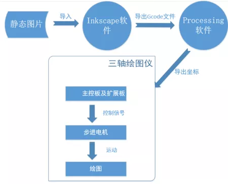
在这里我们采用了一种算法,该算法的思路是:先建立一个平面坐标系,将我们所需要画的图形放置在该坐标系中,这样就可以确定该图形每个顶点的坐标,两个相邻的顶点之间确定一条直线,直线上各点坐标通过插补计算得到,然后画笔依次沿着这些坐标进行移动,完成绘制。所以在这个过程中,我们需要知道如何建立一个图形的坐标系,以及什么是插补计算。插补计算方法可参考 【R311】双轴XY平台-绘制斜向多边形 。
建立坐标系:
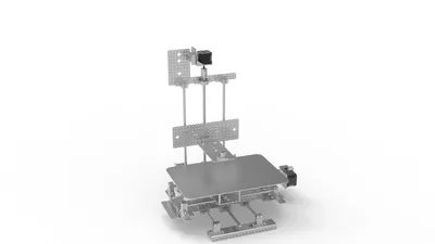
三轴XYZ平台绘图仪,即通过X, Y, Z三轴的步进电机协调控制绘图笔来进行图形的绘制。通过上位机(PC)来发送gcode代码;下位机(三轴XYZ平台绘图仪)通过对接收到的gcode坐标代码进行解析,并通过插补算法来控制各个轴的步进电机进行图形绘制。
本实验将基于三轴XYZ平台利用processing软件处理gcode文件后,进行绘制文字“机器时代”。
3.1硬件连接
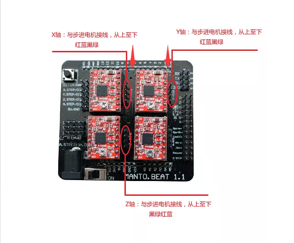
① 各轴步进电机与SH-ST步进电机扩展板的接线顺序如下(从上至下):
X:红蓝黑绿
Y:红蓝黑绿
Z:黑绿红蓝
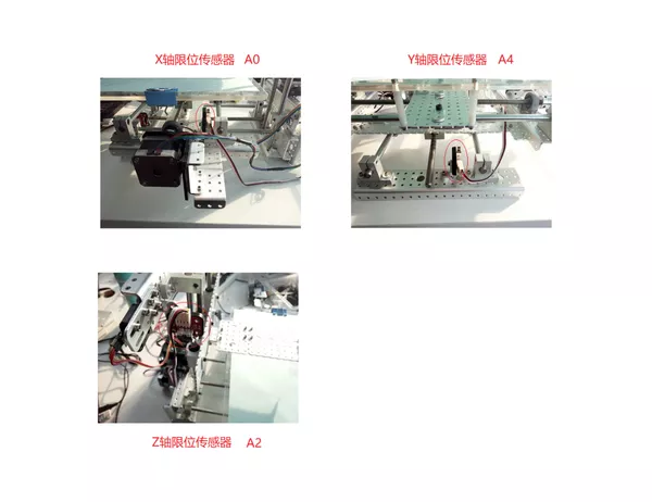
② 各个轴的限位传感器(触碰)与Bigfish扩展板的接线如下:
X:A0
Y:A4
Z:A2
3.2 示例程序
编程环境:Arduino 1.8.19
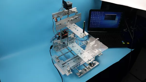
将参考例程代码(_4_smile.ino)下载到主控板中,烧录完成后打开电源,三轴XYZ平台绘图仪各轴步进电机将进行复位,复位完成后,绘图笔将到达绘图区域中心,本实验中三轴XYZ平台绘图仪绘图面积为80*80mm。
- /*------------------------------------------------------------------------------------
- 版权说明:Copyright 2023 Robottime(Beijing) Technology Co., Ltd. All Rights Reserved.
- Distributed under MIT license.See file LICENSE for detail or copy at
- https://opensource.org/licenses/MIT
- by 机器谱 2023-03-30 https://www.robotway.com/
- ------------------------------*/
- #define EN 8 //步进电机使能端,低电平有效
- #define X_DIR 5 //X轴 步进电机方向控制
- #define Y_DIR 6 //y轴 步进电机方向控制
- #define Z_DIR 7 //z轴 步进电机方向控制
- #define X_STP 2 //x轴 步进控制
- #define Y_STP 3 //y轴 步进控制
- #define Z_STP 4 //z轴 步进控制
- boolean DIR; //boolean类型变量 DIR,控制步进电机方向,true为正向,false为反向,根据接线做调整
- int stepper_pulse = 40; //定义步进电机脉冲发送的时间间隔
- #define LINE_BUFFER_LENGTH 512
- const int SENSOR_X = 14; //定义X,Y,Z轴复位传感器引脚
- const int SENSOR_Y = 18;
- const int SENSOR_Z = 16;
- const int stepsPerRevolution = 3200; //定义步进电机每圈转动的步数,细分为16
- float LEAD = 8; //定义丝杠导程,即步进电机转动一圈,丝杠前进8mm
- struct point {
- float x;
- float y;
- float z;
- };
- // Current position of plothead
- struct point actuatorPos;
- float Xmin = -40; //定义绘图区域范围
- float Xmax = 40;
- float Ymin = -40;
- float Ymax = 40;
- float Xpos = 0;
- float Ypos = 0;
- boolean verbose = false;
- void setup()
- {
- Serial.begin(9600); //开启串口通信,波特率为9600
- pinMode(X_DIR, OUTPUT); pinMode(X_STP, OUTPUT);
- pinMode(Y_DIR, OUTPUT); pinMode(Y_STP, OUTPUT);
- pinMode(Z_DIR, OUTPUT); pinMode(Z_STP, OUTPUT);
- pinMode(EN, OUTPUT);
- digitalWrite(EN, LOW);
- resetStepper();
- digitalWrite(EN, HIGH);
- delay(1000);
- }
- void loop()
- {
- delay(200);
- char line[ LINE_BUFFER_LENGTH ];
- char c;
- int lineIndex;
- bool lineIsComment, lineSemiColon;
- lineIndex = 0;
- lineSemiColon = false;
- lineIsComment = false;
- while (1) {
- // 接受来自Grbl的串口数据
- while ( Serial.available()>0 ) {
- c = Serial.read();
- if (( c == '\n') || (c == '\r') ) { // End of line reached
- if ( lineIndex > 0 ) { // Line is complete. Then execute!
- line[ lineIndex ] = '\0'; // Terminate string
- if (verbose) {
- Serial.print( "Received : ");
- Serial.println( line );
- }
- processIncomingLine( line, lineIndex );
- lineIndex = 0;
- }
- else {
- // Empty or comment line. Skip block.
- }
- lineIsComment = false;
- lineSemiColon = false;
- Serial.println("ok");
- }
- else {
- if ( (lineIsComment) || (lineSemiColon) ) { // Throw away all comment characters
- if ( c == ')' ) lineIsComment = false; // End of comment. Resume line.
- }
- else {
- if ( c <= ' ' ) { // Throw away whitepace and control characters
- }
- else if ( c == '/' ) { // Block delete not supported. Ignore character.
- }
- else if ( c == '(' ) { // Enable comments flag and ignore all characters until ')' or EOL.
- lineIsComment = true;
- }
- else if ( c == ';' ) {
- lineSemiColon = true;
- }
- else if ( lineIndex >= LINE_BUFFER_LENGTH-1 ) {
- Serial.println( "ERROR - lineBuffer overflow" );
- lineIsComment = false;
- lineSemiColon = false;
- }
- else if ( c >= 'a' && c <= 'z' ) { // Upcase lowercase
- line[ lineIndex++ ] = c-'a'+'A';
- }
- else {
- line[ lineIndex++ ] = c;
- }
- }
- }
- }
- }
- }
- void processIncomingLine( char* line, int charNB ) {
- int currentIndex = 0;
- char buffer[ 64 ]; // Hope that 64 is enough for 1 parameter
- stepper_pulse = 40; //设置Z轴抬笔落笔时步进电机脉冲间隔
- struct point newPos;
- newPos.x = 0.0;
- newPos.y = 0.0;
- // Needs to interpret
- // G1 for moving
- // G4 P300 (wait 150ms)
- // G1 X60 Y30
- // G1 X30 Y50
- // M300 S30 (pen down)
- // M300 S50 (pen up)
- // Discard anything with a (
- // Discard any other command!
- while( currentIndex < charNB ) {
- switch ( line[ currentIndex++ ] ) { // Select command, if any
- case 'U':
- step(Z_DIR, Z_STP, 2000);
- break;
- case 'D':
- step(Z_DIR, Z_STP, -2000);
- break;
- case 'G':
- buffer[0] = line[ currentIndex++ ]; // /!\ Dirty - Only works with 2 digit commands
- // buffer[1] = line[ currentIndex++ ];
- // buffer[2] = '\0';
- buffer[1] = '\0';
- switch ( atoi( buffer ) ){ // Select G command
- case 0: // G00 & G01 - Movement or fast movement. Same here
- case 1:
- // /!\ Dirty - Suppose that X is before Y
- char* indexX = strchr( line+currentIndex, 'X' ); // Get X/Y position in the string (if any)
- char* indexY = strchr( line+currentIndex, 'Y' );
- if ( indexY <= 0 ) {
- newPos.x = atof( indexX + 1);
- newPos.y = actuatorPos.y;
- }
- else if ( indexX <= 0 ) {
- newPos.y = atof( indexY + 1);
- newPos.x = actuatorPos.x;
- }
- else {
- newPos.y = atof( indexY + 1);
- indexY = '\0';
- newPos.x = atof( indexX + 1);
- }
- drawLine(newPos.x, newPos.y );
- // Serial.println("ok");
- actuatorPos.x = newPos.x;
- actuatorPos.y = newPos.y;
- break;
- }
- break;
- case 'M':
- buffer[0] = line[ currentIndex++ ]; // /!\ Dirty - Only works with 3 digit commands
- buffer[1] = line[ currentIndex++ ];
- buffer[2] = line[ currentIndex++ ];
- buffer[3] = '\0';
- switch ( atoi( buffer ) ){
- case 300:
- {
- char* indexS = strchr( line+currentIndex, 'S' );
- float Spos = atof( indexS + 1);
- // Serial.println("ok");
- if (Spos == 30) {
- step(Z_DIR, Z_STP, -2000);
- }
- if (Spos == 50) {
- step(Z_DIR, Z_STP, 2000);
- }
- break;
- }
- case 114: // M114 - Repport position
- Serial.print( "Absolute position : X = " );
- Serial.print( actuatorPos.x );
- Serial.print( " - Y = " );
- Serial.println( actuatorPos.y );
- break;
- default:
- Serial.print( "Command not recognized : M");
- Serial.println( buffer );
- }
- }
- }
-
- }
- //直线插补函数,参数为点坐标值
- void drawLine(float x1, float y1)
- {
- int dx, dy, n, k, i, f, stepInc;
- stepper_pulse = 150; //设置步进电机写字时脉冲间隔
-
- if (x1 >= Xmax) {
- x1 = Xmax;
- }
- if (x1 <= Xmin) {
- x1 = Xmin;
- }
- if (y1 >= Ymax) {
- y1 = Ymax;
- }
- if (y1 <= Ymin) {
- y1 = Ymin;
- }
-
- x1 = (int)(x1/LEAD*stepsPerRevolution);
- y1 = (int)(y1/LEAD*stepsPerRevolution);
- float x0 = Xpos;
- float y0 = Ypos;
-
- //Serial.println(Xpos);
- //Serial.println(Ypos);
-
- dx = abs(x1-x0);
- dy = abs(y1-y0);
- n = abs(dx+dy);
-
- if(dx==0||dy==0)
- {
- stepInc = 1;
- }
- else
- {
- stepInc = 10;
- }
- if(x1 >= x0)
- {
- k = y1 >= y0 ? 1:4;
- }
- else
- {
- k = y1 >= y0 ? 2:3;
- }
-
- for(i=0,f=0;i<n;i+=stepInc)
- {
- if(f>=0)
- {
- switch(k)
- {
- case 1:
- step(X_DIR, X_STP, stepInc);
- f = f - dy;
- //Serial.println("+x");
- break;
- case 2:
- step(X_DIR, X_STP, -stepInc);
- f = f - dy;
- //Serial.println("-x");
- break;
- case 3:
- step(X_DIR, X_STP, -stepInc);
- f = f - dy;
- //Serial.println("-x");
- break;
- case 4:
- step(X_DIR, X_STP, stepInc);
- f = f - dy;
- //Serial.println("+x");
- break;
- default:break;
- }
- }
- else
- {
- switch(k)
- {
- case 1:
- step(Y_DIR, Y_STP, stepInc);
- f = f + dx;
- //Serial.println("+y");
- break;
- case 2:
- step(Y_DIR, Y_STP, stepInc);
- f = f + dx;
- //Serial.println("+y");
- break;
- case 3:
- step(Y_DIR, Y_STP, -stepInc);
- f = f + dx;
- //Serial.println("-y");
- break;
- case 4:
- step(Y_DIR, Y_STP, -stepInc);
- f = f +dx;
- //Serial.println("-y");
- break;
- default:break;
- }
- }
- }
- Xpos = x1;
- Ypos = y1;
- }
- /*
- //函数:step 功能:控制步进电机方向,步数。
- //参数:dirPin对应步进电机的DIR引脚,stepperPin 对应步进电机的step引脚, steps 步进的步数
- //无返回值
- */
- void step(byte dirPin, byte stepperPin, int steps)
- {
- digitalWrite(EN, LOW);
- boolean DIR = steps>0 ? true : false;
- digitalWrite(dirPin,DIR);
- for(int i=0;i<abs(steps); i++)
- {
- digitalWrite(stepperPin, HIGH);
- delayMicroseconds(stepper_pulse);
- digitalWrite(stepperPin, LOW);
- delayMicroseconds(stepper_pulse);
- }
- digitalWrite(EN, HIGH);
- }
- //步进电机复位函数
- void resetStepper()
- {
- stepper_pulse = 40; //设置步进电机复位脉冲间隔
-
- while(digitalRead(SENSOR_Z))
- step(Z_DIR,Z_STP,10);
- step(Z_DIR,Z_STP,-15);
- while(digitalRead(SENSOR_X))
- step(X_DIR,X_STP,-10);
- step(X_DIR,X_STP,15);
- while(digitalRead(SENSOR_Y))
- step(Y_DIR,Y_STP,10);
- step(Y_DIR,Y_STP,-15);
- //复位笔至平台中间位置,步数根据中间位置距离复位传感器的距离计算
- step(X_DIR, X_STP, 28000);
- step(Y_DIR, Y_STP, -16000);
- step(Z_DIR, Z_STP, -30000);
- }
3.3 图形绘制
接下来我们将通过上位机的processing软件发送生成文字“机器时代”的 gcode文件给三轴XYZ平台绘图仪进行图形绘制。
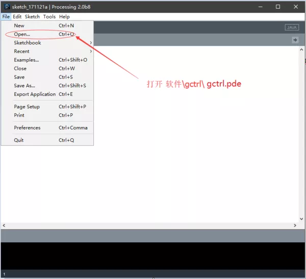
首先将 软件资料包\processing-2.0b8.zip 文件解压到电脑上任意磁盘,然后打开processing.exe来启动 Processing 软件,之后按下图所示步骤进行操作:
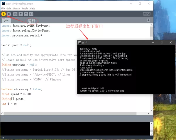
此时打开绘图仪电源开关,在英文输入法状态下按键盘P键,选择端口号,等待三轴XYZ平台绘图仪复位完毕,进入接收上位机指令状态;然后英文输入法状态下按键盘G键,选择之前生成的 gcode文件,点击确定,开始发送gcode文件代码,三轴XYZ平台绘图仪开始绘图;三轴XYZ平台绘图仪在绘图过程中,可以按X键来停止发送gcode文件代码。
注意事项:
① 关于绘图笔的安装,可以让绘图仪进入工作状态后关闭电源,此时安装绘图笔使其与纸面相接即可。
② 程序中步进电机使用的细分数为16细分,无细分时200步/圈,16细分即 3200步/圈。
③ 生成gcode坐标文件后,使用windows的笔记本或者Notepad++软件打开gcode文件,然后删除第一行和第二行,如下图所示:
4. 资料下载
资料内容:
①绘制空心字-例程源代码
②绘制空心字-样机3D文件
③软件资料包
资料下载地址:https://www.robotway.com/h-col-202.html
想了解更多机器人开源项目资料请关注 机器谱网站 https://www.robotway.com
|


 发表于 2023-4-18 09:30:25